Table of Contents
UPB: Universal Powerline Bus
Installing the Interface
 XTension supports the RS232 PIM (Powerline Interface Module) but not the USB variety. It can be connected through any USB Serial Adaptor And may be able to be connected over a TCP/Serial adaptor like the Wiznet cards that XTension supports. The UPB Pim requires 5v power to be applied to the DTR line to power it’s internal level shifters and not all ethernet/serial adaptors can supply enough current to make a connection. The Wiznet card can be altered to provide this see wiznet alteration for more info.
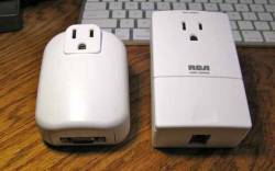
This picture shows the relative size and compares the UPB RS232 PIM device on the left to the X10 CM11a interface on the right.
Configuring the Interface
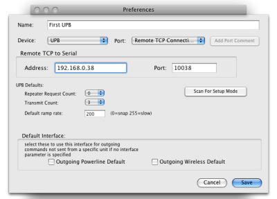
 Open the preferences window in XTension and create a new interface. Select “UPB” as the interface type and you'll be presented with a few UPB specific settings. Here you'll set the system defaults for the repeater count and transmit count. These settings can be overridden for individual units, but for any that set the default the value will be taken from here. The default ramp rate will be sent if no unit specific ramp rate is set or no ramp rate is specified in the applescript commands being used. Finally the “Scan for Setup Mode” button is used to create new units in XTension to correspond to a UPB device that you've manually placed in setup mode.
Setting up Units
You can create 3 different kinds of units in XTension for UPB devices. You can create a unit that sends direct commands to a specific UPB unit by address, this is a “direct” unit. You can create a unit that responds to and sends link commands, a “link” unit and lastly you can create a special unit that will be filled in with the noise level as reported by the interface, most on this in the section below entitled “doing a site survey”.
UPB Addresses and XTension
The address as entered in XTension can have 2 formats. 4 characters or 6 characters depending on the capabilities of the device you're controlling. The first 2 characters are the hex value of the network ID of the device. Similar to the house code of an X10 device, but 2 characters instead of just one since UPB supports so many more network ID's. The second 2 characters are the Unit ID in hex, similar to the X10 unit code, but 2 characters instead of just 1. So the address of a UPB appliance module might be “FFCD” for a network ID of FF and a unit id of CD. If the device has multiple channels then you would create a unit for each channel with the same network ID and unit code, but add in another 2 characters for the channel of the device. For example a 2 load light switch would be controlled by creating 2 units with the address “FFCD01” and “FFCD02” each section must have 2 characters so if the unit ID is just 9, you must enter “09” like “FF09”.
XTension can fill in this information for you. Go to the unit in question and place it into setup mode. If it's a module click the button 5 times, if it's a light switch click the up paddle 5 times. For other devices follow their instructions for manually entering setup mode. Once the device or devices (you can do several at a time if you like, but that might get confusing) return to the XTension computer within the 5 minute timeout and click the “Scan for Setup Mode” button in the preferences window for the interface. New unit dialogs will popup with the address and network ID and network password filled in. Setup any other features of the unit, give it a name and save it.
A link unit cannot specify a channel, so only 4 characters are allowed for a link unit.
Sending Commands
I've added “rate” as an optional parameters to the dim/bright turnon turnoff applescript verbs. So you could send:
turnoff "my upb unit" rate 30
if you dont specify a rate in the command the unit will fall back to it's defaults. If a value is set in the unit setup dialog it will use that and if default is selected then the interface defaults will be used. If you control the unit with the programs user interface then the defaults for ramp rate will be used until the UI is updated to allow entering of the ramp rate somewhere.
As of this beta all dim/bright on/off commands use the UPB goto command. If there are devices that require it, or if there is some other reason I should support the fade command instead please let me know. I can't see that there is really any difference except when manually dimming a device via a remote you can issue a fade start and then a fade stop and not have to worry about the level.
build 770 also adds the blink command.
Blink "UPB unit name" rate 5
watch out for strobe effects at low values.. to stop a unit blinking send it an on or an off.
Query Support
UPB modules are all 2 way and can be queried by XTension for their current value. The same verb used for querying X10 2 way modules is used for UPB modules.
query "my upb unit" [with no wait]
if you include the “with no wait” optional parameter then the script will continue and not wait for the unit to respond. If the device responds the database unit will be updated with any change to the value whenever the unit responds. Please note that the ON/OFF scripts are not run for a response to a query even if the values are different. The database is simply updated to reflect the new real value. If you do wait for the return then the value is also returned to the script so you could do something like:
write log "the value of the unit is " & (query "my upb unit")
and the script will pause and wait there for the unit to respond, or timeout in 30 seconds and error if no response is received. Please note that this timeout is from the time the command is issued, not necessarily from the time the interface actually places it on the powerline. If you have just run your going to bed script and placed 300 turnoff commands into the queue the query might timeout before the interface actually got around to sending the command.
Link Support
The second choice for a device type in XTension is a UPB Link. This unit will follow any link activate/deactivates it receives from the network and run it's scripts and also will send link activate/deactivate commands as you control it. There is no automatic setup for a link object since it is an idea, not necessarily connected to a single physical device. You can find the link address that a device sends by just having XTension running and sending the link activate command, it will be logged as having been received in the XTension log and then you can create a unit to reference that network id and unit id. For example, it seems that the new light switches by default do not just report their level changes when you tap on them, but rather send a link packet with the same address as their direct address. (at least this is how the ones I've received to work with behave by default) in order to follow the physical action of the switch it would currently be necessary to create a link object and a direct object with the same address. The link object would tell you if someone manually pressed the paddle and the direct unit would be used for controlling the switch. XTension has added 2 verbs to help with linking:
add link "name of link unit" to unit "name of UPB Direct unit"
delete link "name of link unit" from unit "name of UPB Direct unit"
It is no longer necessary to manually put the units into setup mode, as long as the network password for the unit is filled in XTension will place them into setup mode prior to sending the add or delete link commands.
UPB Devices and Discussion
UPB Devices are highly programmable. Not every possibility is fleshed out in the beta version yet. A light switch may be setup to send a link as discussed above, or it may be configured to send an update of it's status when it's controlled manually. If you're integrating into an already setup UPB network then XTension will probably need a link unit to follow the actions. if you're setting up from scratch then you may prefer to reprogram the switch to just send an update. This way your XTension unit will receive the status or value change update the database and run it's on/off script. You can then use that from there to do any other light programming that you wish. I imagine that different boxes and programs out there will all make use of these various capabilities in different ways and as I learn from the beta folks what that is I'll do my best to be able to follow what's going on in XTension. As of the first beta the individual units assigned to links are not automatically updated unless the unit is programmed internally to send it's updates in response to receiving of a link. I dont know if this is a default or common setup yet, we're still learning how best to set this up with XTension. The goal is to have a system that can piggyback and add functionality to an existing UPB network, as well as be the main controller for one all by itself without becoming too complicated. Much of the complexity of the UPB devices is only necessary if you're setting up scenes without a computer or with one of the various alarm panel/lighting control systems that have a limited scripting system in them. So a system starting from scratch in XTension can offload much of the logic for scenes and links to the computer for those that prefer to edit such things on the screen rather than by walking around and adjusting link levels manually at the switches. This part of the implementation is in flux as I figure out just how some of these other folks are using it.
Site Survey
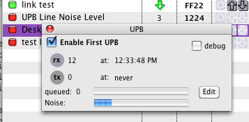
 One of the great features of the UPB interface is the ability to listen to the line noise levels and report that. XTension will make this data available in 2 ways. In the interface status floating window a new progress bar is displayed showing the noise level which is updated every 5 seconds. you can also create a unit to hold the current value of the noise. Create a new unit and set it's device type to “UPB Noise Level” no address is required, though a quirk in address processing to be fixed in a future beta requires that the address be not empty, so put a 1 in there or something. This unit will now receive updates (potentially filling your log with a lot of unit updates) and in combination with XTdb: Database and Graphing for XTension graph the noise level over time for site survey or just debugging help.
How the noise level is calculated?
Xtension works with the PIM in “pulse” mode in which all the activity from the power line is logged and tracked. If the PIM believes a pulse has been received it will send a signal to XTension with the strength of that pulse. If the pulse does not become a valid start of a packet then it's logged to the noise level buffer. If an idle, or no pulse, signal is sent to XTension a 0 is added to the noise level buffer for that period. Every 5 seconds the noise levels are added up and averaged. Signal strength for the pulses that do become part of a valid message are also stored and averaged for the entire packet received. This data is available in the ON script via the “signal strength” verb so you can log the strength or check for dropouts via scripts if you wish. Valid packets are not considered part of the noise level calculation as one would hope they would be much higher than the noise.
What makes the noise?
I have discovered a couple of ways to cause UPB some pain and more info is on the Debugging UPB page.
Mixing with X10 or whatever
There should be no problem running both a UPB and an X10 interface on the same system. XTension's multiple interface support will allow you to add UPB to the system and gradually convert existing units as you see fit. There is no reason to make a clean break from X10 or anything else all at once. Though the X10 and UPB signals do not cause each other any problems, sometimes the X10 dimmers can create enough UPB noise to be a problem. See the section on debugging for more info.

