Table of Contents
PWM Dimmer: Neopixel Indicator Settings
A short string of Adafruit Neopixels or other compatible, individually addressable LED’s may be hung off a GPIO line in order to provide status indication or flashing color alerts and such. Compatible devices include, but are not limited to anything based on the WS2812, WS2811, SK6812 and possibly though untested as of this writing the APA106. There may be others as well that are supported by the library. These are all devices with a single data line and 2 power lines. If the LED has both a data and a clock pin then these are not compatible. Compatible devices are available in many form factors. LED Strip Lights, 5mm, 8mm and “straw hat” versions as well as the same led’s used on the strips attached to various small boards of many sizes and shapes. LED’s that have a separate white channel are also supported.
Do to timing and memory issues you should limit the number of LED’s connected this way. It may be possible to get as many as 30 working, but this would likely cause other issues with memory or the smooth running of fades and such.
This does not provide for fancy animations or displays, just basic setting of color and brightness as well as being able to flash between colors or to fade from one to another.
You should read, understand and follow all of the connection and usage guidelines on the Adafruit NeoPixel Überguide This is very important to avoid damaging the LEDs or your PWM Dimmer board.
Powering Your NeoPixels:
Most LEDs of this type call for powering with 5v. I have not yet found a type that did not run just fine on the 3.3v supplied by the built in power supply of the PWM board. While running on this lower voltage the maximum brightness may be reduced somewhat and the color rendering will not be as accurate as it would be otherwise. I dont find this to be a problem for me at all as I’m not using these as general illumination but as alerts or indicators in various places.
If you have a 12v string, or power them from a separate 5v supply then you must follow Adafruits instructions linked above including the use of a level shifter to protect the PWM Dimmer from the higher voltage potential at the LED’s.
You must provide the resistor to limit current being sent to the LED’s data pin. Again as discussed on the excellent Adafruit site.
Configuration:
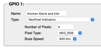
 After selecting NeoPixel indicator on the GPIO settings page there are a few other items to setup.
One hopes that the Number Of Pixels field is self explanatory.
The Pixel Type lets you select from all the different combinations supported by the Excellent Adafruit Library. This includes many more combinations than probable exist in the real world, but different manufacturers and form factors often have setup their devices in different ways. The default for all the Adafruit LED strips is “NEO_GRB”
After setting up try setting one of the connected LEDs to individual colors of red, green, blue and if supported white. If the colors correspond then you got it right. If the wrong colors are displayed then you will have to find the correct ordering in this popup. Setting it wrong will not harm anything they just wont work properly.
Buss Speed is going to be the default of 800khz for almost all devices available. Only the oldest WS2811 chips required the slower buss speed though it is included as a setting in case you still have a bunch of those laying around that you wish to use.
Scripting Commands:
TBA…
