Table of Contents
WiFi 1-Wire Host Kit
The XTension 1-Wire Host Kit can read up to 16 Dallas 1-wire digital temperature sensors and send their readings over WiFi to Units in XTension. The firmware is open sourced, Arduino compatible and runs on an ESP8266 based processor.
Jump to the Build Instructions
Purchase the WiFi One Wire Host Kit:
Please note before you purchase that this kit works directly with XTension. Please verify that you can use it with your Home Automation system of choice before purchasing. At the moment I am shipping only to US addresses. Please contact me directly for information on shipping to Europe or other countries.
Power Requirements:
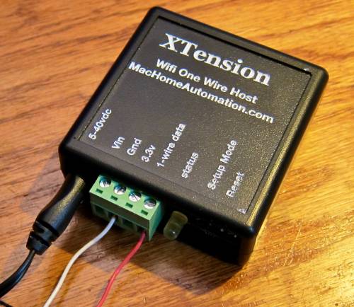
The built in switching regulator means that you can power the device with virtually any power supply that delivers between 5 and 40VDC through a standard 3.5mm barrel jack. The Vin and GND of the power supply input are also brought out to the 4 pin removable header so in case a barrel jack power supply is not handy or you already have other power available at the install site you can use that. NOTE: with version 1 of the hardware there is no polarity reversal protection diode on the board. Please verify that Vin is connected to the positive output and that GND is connected to ground or the device may be damaged.
This is not a battery operated project, it requires a stable DC power source.
Some 5v power supplies that sag even a tiny amount may not be able to provide enough power to the device. I would recommend at least a 6v power supply though some 5v supplies do work.
Connecting 1-Wire sensors:
Dallas 1-wire temperature sensors can be connected in either powered mode using the GND, 3.3v and 1-wire data pins, or in parasitic power mode using only 2 wires of 1-wire data and GND. All sensors connected must be either powered or in parasitic mode, the 2 cannot be mixed together.
Only 1-wire temperature sensors are supported, no other 1-wire devices should be connected to the network. While any currently available sensor should work fine I recommend one based on the DS18B20 sensor. The resolution is limited to 1 decimal point so attaching a more sensitive and expensive sensor will not gain you any more usable data.
Connecting up the 1-wire network should be done according to Dallas’s best practices either in a linear chain or a star network. Other more random configurations of sensors do work but may generate more errors or failed reads. For very long networks it may be helpful to add an RC filter at the sensor end and those with very long wires outside may benefit from a lightning arrestor on the input to the reader. Even if the wires are not directly struck a nearby strike can induce a huge amount of current into a long wire burning out the CPU. Since the CPU is socketed it could be replaced without having to replace the entire board assuming that the power supply portion of the board is not equally destroyed.
Initial Setup:
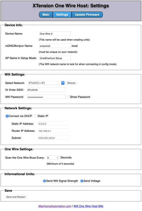
 Upon the first powerup or anytime you press the “setup” button the device will go into setup mode. When in setup mode the “status” led will flash slowly. Two seconds on and two seconds off to let you know that it is in setup mode. When in setup mode it will create it’s own WiFi access point named by default “OneWireHost Setup” to do your initial setup you need to join this wifi network either from a computer or a phone or other mobile device. Once you’ve joined the network open a browser and visit http://192.168.4.1/ this will open the main web interface to the device. Click the “Settings” link in the navigation bar at the top to be able to select a wifi network for it to join and setup it’s other settings.
Device Name: this is the name of the device that will be sent to XTension. All the units will use this as a prefix so it should be something descriptive but with a maximum of 30 characters. “East Attic Temps” or “Basement Sensor” or something similar.
mDNS/Bonjour Name: This is the name it will register on the network. It must be 30 characters or less, contain no spaces or other special characters and be unique on the network. The default is “onewire” which will mean you can visit it’s configuration at anytime by entering “onewire.local” into any browser also on the local network.
AP Name in Setup Mode: When in setup mode the name of the Access Point that will be created.
Select Network: When the settings page is opened the device will automatically do a scan for available WiFi networks. You can scan again at any time by hitting the “Rescan” button. Select a network from the list or manually enter the name into the SSID field below.
Or Enter SSID: If your network is “hidden” or you are setting up a device to connect to a WiFi network that is not available at the moment you can manually enter the name of the network into this field. If you select a network from the popup this field is populated automatically.
WiFi Password: Enter the password of the wifi network. If you check the “show password” checkbox the field will show the actual characters instead of replacing them with dots as in the example image.
Connect via… The device can use your DHCP server to assign an address or you can setup a static IP address. A Static IP address is not necessary for connecting via XTension but may be useful if you wish to be able to connect to the web interface without using the mDNS address or are using some other system for connecting to the data stream. For a standard XTension install you may leave the “Connect via DHCP” selected and ignore the remaining settings.
One Wire Settings: how often would you like to scan the 1-wire bus in seconds. The minimum setting is 5 seconds but might need to be longer if you have many sensors as it does take them some time to prepare their readings. If the temperature reading has not changed from one reading to the next no update will be sent to XTension. If the value has changed then the Units in XTension will receive a new value when this interval expires.
Informational Units: You can optionally send the WiFi Signal Strength and Power Supply voltage levels to XTension units. If these checkboxes are turned on a Unit will be created in XTension to hold the values automatically and will be updated at the same interval that you have entered for scanning of the 1-wire bus above.
Once you have completed the setup please click the “Save and Restart” button, If you are in setup mode and have selected a wifi network to join the web page will not refresh. You will have to visit the device on the new network and at the new mDNS or IP address that you have changed. If you made changes to the settings without changing the addresses or wifi settings then the page will wait for the device to reboot and will reload with the new settings so you can verify that they have been saved and are working.
Main Interface:
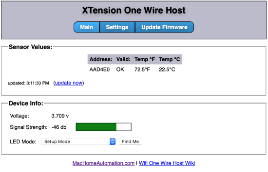
 When you connect to the device via a browser the first page that displays will show you all the connected sensors, the power supply voltage as well as let you change the LED mode. You can also click the “Find me”button to start flashing the LED quickly in case you have multiple devices and need to know which one you’re talking to.
At the top of the main page will be a list of all the 1-wire sensors that were found at powerup. Whenever one has a change in it’s value it will highlight for a moment and fade out to show you more obviously that a value has changed. Below this list is a timestamp showing when it last successfully was able to poll the device for updates and a link to force a poll right now.
Device Info:
The Voltage and Signal Strength are displayed below the temperature readouts. The power supply voltage output should be around 3.7v under most normal circumstances.
LED Status Patterns:
When the device powers on or reboots the LED will do a “breathing” signal, Fading in and out twice to show that the proper firmware is loaded. Once the firmware is loaded and running the LED will flash once a second on and then off as it is searching for and trying to connect to the WiFi network. If the device hangs at this point and continues to flash once a second then your settings for the WiFi network may be incorrect or it may not be able to reach the network. Please press the Setup button to re-enter setup mode, reconnect with your phone or computer and try running the setup again.
Once the WiFi network has been joined the default is for the LED to turn off. If it is not flashing yet the power is on then all is working properly. On the main page of the web interface you can change the LED mode to whatever you wish but likely the “flash when reading sensors” will be the next most useful setting. In this mode the LED will flash for a moment as the 1-wire bus is being read.
Firmware Updates:
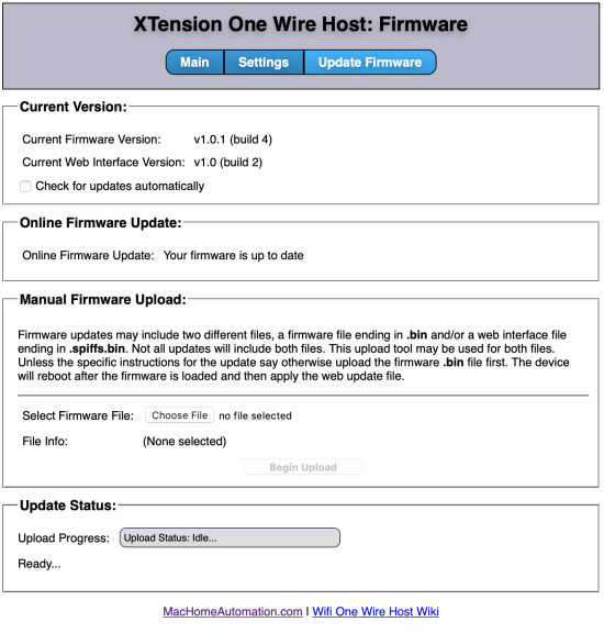
 Firmware updates can be sent to the device in 2 ways. When you load the Firmware page it will automatically attempt to download a small JSON file from the MacHomeAutomation.com site that includes the most recent firmware builds and direct links to the files. No firmware update will ever be done automatically but it will tell you if a firmware update is available or not. You can then click the Update Now button to begin downloading and installing the firmware files from the webpage.
Alternatively you can download the firmware files yourself and upload them to the device via a standard file upload interface on the Update Firmware page.
A firmware update will normally be made up of two files. A firmware file and a web interface file. Unless the specific instructions for the update say differently you should apply the firmware update first and the web interface update second. If you do the update automatically over the internet then you do not have to do this twice. The new firmware will be loaded, the device will reboot and then the web interface file will be applied and the device will reboot again.
Once both files have been applied the page will reload and you should get the “Your firmware is up to date” message.
Firmware Security:
The firmware is delivered in compiled and digitally signed form. No firmware from anywhere else can be installed on the device. If you wish to develop your own firmware for the device you must have a programming cable for an ESP-01 chip in order to load an unsigned or differently signed firmware onto the device.
Physical Mounting Options:
By default the device ships in a black project box with the bottom open to allow reaching the power and other connectors and headers. It is also available with an optional DIN rail mounting board.
XTension Settings:
The minimum XTension supported by this kit is 9.4.26.
Once the device is on the network you can configure XTension to talk to it and receive its temperature values. In the Interface List window in XTension create a new instance of the “XTension Kits” plugin and then enable it. Only a single instance of this plugin running is needed to receive data for any number of XTension branded devices. It is not necessary to enter the IP address or mDNS name of the device anywhere. Any XTension devices on the network will find up to 4 different XTension instances running on the local network. The necessary units will be created automatically and you will begin receiving temperature updates immediately.
One Unit will be created that represents the device itself. This unit will be on or off showing the availability of the kit on the network. It also contains any global settings necessary for the device. In the case of the 1-wire sensor kit the only available option is if you wish it to report it’s units in C or F.
In addition to this top level Unit a unit for each 1-wire sensor will also be created. The 1-wire bus is scanned for new units regularly but you should power it off or disconnect the removable header while changing wiring to keep from shorting the power supply or other things that may damage the device. After re-connecting the 1-wire bus or restarting the device it will rapidly locate any new sensors added to the bus and create Units for them.
Building the Kit:
The kit is available pre-assembled for an extra charge. If you’re assembling it yourself please see the detailed instructions on the Build Page.

